All projectsDirectional speaker
Simulation
The AM drive signal
Build and analyse the amplitude-modulated signal a parametric speaker sends, then see why plain AM distorts and how preprocessing fixes it.
Goals
- Generate an AM signal, find its three spectral lines, and check them against the product-to-sum identity.
- Choose a sample rate that can carry a 60 kHz carrier plus its sidebands without aliasing.
- Predict the audio distortion of plain AM with Berktay's result and compare it with square-root AM.
Why this matters
The department’s speaker does this modulation inside its own electronics, so you won’t program it. The modulation scheme still decides how loud and how distorted the audio is, and it is the input to your KZK simulation, which uses plain AM: a 60 kHz carrier modulated by a 1 kHz tone.
The physics
Plain amplitude modulation multiplies the carrier by an envelope:
So the spectrum has exactly three lines: the carrier and two sidebands away from it. To store or play it without aliasing, the sample rate must exceed . For a 60 kHz carrier modulated by 1 kHz that means more than 122 kHz, so 192 kHz audio hardware.
The parametric array does not hand you back. From the previous step, the audio is proportional to . With , the squared envelope contains a term, and after two time derivatives its amplitude relative to the fundamental is . Full modulation gives as much second harmonic as signal. Square-root AM fixes this by driving with
so is linear in the audio . The price is that has an infinitely wide spectrum, and the ultrasonic transducers in a real speaker only pass a few kHz around their resonance.
Hints
Hint 1Reproduce the three lines first
Run directional_speaker_am.py with the defaults and find the carrier and both sidebands in the spectrum. Then change the duration and watch the peak width. The manual’s resolution formula, , should predict what you see.
Hint 2Find out what the department speaker does
Look up the model’s manual or datasheet: its carrier frequency, what input it takes, and whether it mentions distortion or preprocessing. If it uses square-root AM or single sideband, a plain-AM simulation will overestimate its distortion. Note that in your paper.
Hint 3Simulate the demodulation, don’t just trust the algebra
Add a function that computes numerically for plain AM and for square-root AM, then take its spectrum. Then band-limit to roughly the transducer bandwidth before squaring. How much of the improvement survives?
What past teams did
2026–27 team
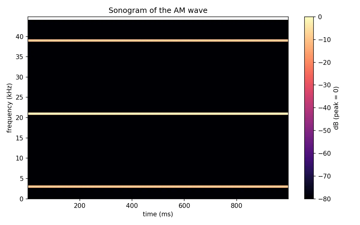
We wrote directional_speaker_am.py, a Tkinter app that generates the AM signal, plots the waveform and spectrum, plays it and exports a WAV file. The sample rate is picked automatically from the standard audio rates so it stays above twice the upper sideband. The defaults (21 kHz carrier, 18 kHz message) put the lower sideband at 3 kHz, which is what the sonogram above shows. The manual in the resources list explains every function.